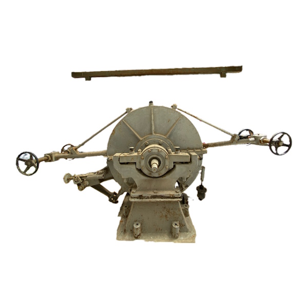
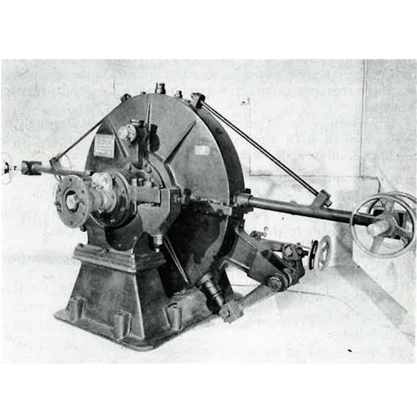
The dynamometer brake is a device used to generate the resistant load necessary for the experimental measurement of the performance of an engine.
In the past, the most widespread dynamometer, especially for high power applications, were the hydraulic ones, in which the resisting load is generated by the viscous friction due to the motion of an impeller immersed in a liquid (generally water).


In older brakes, the impeller is made up of one or more rotating discs, included between fixed discs integral with the stator. The space between fixed and mobile parts is very small, so the interposed water is dragged in a vortical motion by the impeller: the water heats up (due to internal friction) and the work done by the engine is transformed into heat. By continuous circulation of water through the brake, the heat generated is dissipated outside. To increase braking resistance, the discs are generally drilled. The resistance opposed by water to the rotation of the rotor reacts on the stator, producing a torque equal and opposite to that one generated by the motor. This torque is calculated starting from the measurement of the force with a dynamometer, which counteracts the rotation tendency of the stator, once the arm of application of the force itself is known with respect to the rotation axis. The adjustment of the resistant load is obtained by varying the water level inside the brake. The brake rotor is connected directly to the engine via an elastic shaft coupling and the power is calculated by measuring the driving torque and the rotation speed of the engine.Hydraulic dynamometers are very simple to use. They are suitable for both modest torques (powers of a few kW) and very high torques (powers of thousands of kW).
A publication of 1984 concerning the history of the Institute dated the brake to 1930.
Probably this brake was donated to the institute, but there is not official documentation, also considering that at the time the activities carried out had mainly military purposes.
